My design will make use of a tube-and-lug structure, the likes of which are typically seen on steel bicycle frames; however, the lugs themselves will be made entirely out of components that have been 3D printed. This will be accomplished by using a combination of a tube-and-lug structure and a tube-and-lug structure. The framework will be analogous to what is typically found on the frames of steel bicycles. The first thing I will do, which will also be the first step in the process, will be to lay out the geometric framework of the frame. After that, I'll proceed to the following stage in the process. Because of this, I will first be able to build a model of the m3 press nut in two dimensions, and then, with the assistance of the self clinching rivet nut in two dimensions, I will be able to build a of the in three dimensions. utilizing the in only two dimensions. Over the course of the past few years, one of the programs that I have used the vast majority of the time is called Fusion 360, and it is also one of the programs that I recommend to others. I began the process from the very beginning and worked my way through it. Because the actual carbon fiber materials that I will be using are so much more expensive, I will be making the prototypes of all of these different parts out of ABS rather than using those materials. This is because ABS is significantly less expensive than carbon fiber. This is because the actual carbon fiber materials that I will be using are going to be a lot more expensive than the ABS that I will be using. One the one hand, I do not need a wall that is built to be quite as thick as it is at the moment. It is not necessary for me to attach it here because I will not need to do so as long as there is a significant amount of thickness on the inside. I will not need to do so. Hearing you talk about it has led me to the realization that it is not something that is necessary for me either, which is a result of the fact that I heard you talk about it. As a result of the amount of work that would be required, I have not even bothered to print it out as of yet.
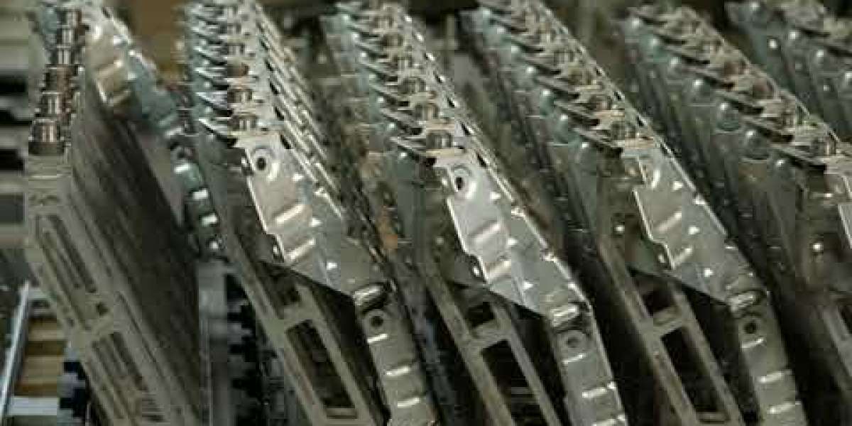
 Haeger 618 Robot cellhttps://www.youtube.com/watch?v=XxpVQGtBi-I
This particular illustration shows a design for a flow curve that is both more technically advanced and more pleasing to the eye than the one that came before it. When we reached this stage of the process, my background in surface modeling and the experience I've gained working with it began to come in very useful. Obviously, this component needs to be there, and once that is taken care of, you will be able to move on to the fourth iteration: at the moment, I have only just begun working on improving the geometric structure of the tube shape matching, logo layout, and overall printing quality, and I am very pleased with the way that it looks. To say the least, that blows my mind completely. Despite the fact that you need a large variety of materials in order to connect all of them together, the aesthetics of the bike frame are very appealing to me. This is despite the fact that you need a lot of different kinds of materials. The bike's frame has a very appealing design to it, in my opinion.
During the second iteration of the design, I attempted to carve the company logo into the back of the card using one of the tools available, but the outcome was less than ideal. It is not reasonable for you to be surprised by the lack of part cooling or the size of the nozzles; therefore, you should take precautions to ensure that neither of these things occurs to you. As soon as that is out of the way, we can move on to discussing the material that the prototype is made of, which is a material that has a lilac color to it. The subsequent subject that will be discussed is the proper placement of the mounting area for the rear brakes, which can be found in the vehicle. This would be a part in a normal circumstance; however, in order for me to print it, the surface that it rests on must be smooth. Additional citations are required. After I've finished putting everything else together, I'll start by attaching the bottom bracket. If that doesn't make it feel safe enough, I'll try using some hot glue to see if I can make it stay put for the length of time required to pass the test.
Another extremely challenging component, but my surface technology: our surface treatment technology is a little similar to their own, self clinching rivet nut there are some good continuous curves, and I am not entirely certain about the tire clearance, but this is exactly why we make prototypes:for the purpose of making the bottom bracket look cool, for the purpose of making the bottom bracket look cool, for the purpose of making the bottom bracket look cool, for the purpose of making the bottom bracket look cool, for the purpose of making the bottom bracket look cool, for the purpose of making the bottom bracket look cool, for the purpose of making the bottom bracket look cool, for the purpose of making the bottom bracket look cool, for the purpose of making the bottom bracket look cool, for the purpose of making the bottom bracket look cool, for the purposeThe threaded bottom bracket for actual falling off and the rear falling bracket are the final two major components that need my attention to design. Both of these brackets are falling off. com are what end users make use of. It is not necessary for you to create these general parts on your own because this is a very cool tool for constructing frameworks, which will save me a lot of time. Consequently, you do not need to create these general parts on your own. As a consequence of this, there is no requirement for you to develop these general parts on your own.
When cutting certain pipes, it is necessary to use a variety of different angles at various complex proportions. All aspects of its appearance have been given a high level of attention to detail. On the other hand, the seat tube that can be found below has a few flaws that need to be fixed in order for it to be used properly.
Installing the seat bracket is the very first thing that needs to be done in order to move on to the next step. I sincerely apologize in advance for any inconvenience this may cause you, but the supports for the chains are located over here, self clinching rivet nut and the supports for the seats are located over here. This is of utmost significance due to the dangers that are involved. It is possible to state with complete assurance that this much is true.
You will be able to see it in real life with the same degree of clarity that you have when looking at it on the computer screen, once you have finished the first step of putting it together, you will be able to see it for yourself. After you have completed this procedure, you will be able to observe it in its actual setting. The mind-bogglingly incredible coolness of it completely boggles my brain. According to my assessment, it possesses the appropriate level of strength to accomplish what needs to be done.


